Return to flip book view
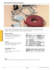
Pipe Conduit Clamps Hangers Pipe conduit clamps hangers Our beam attachments and pipe supports offered in this section are designed to provide supports without drilling or welding A complete selection of beam clamps pipe clamps rollers supports and accessories are designed for use with our channels and offer many installation advantages Materials Finishes Pipe clamps pipe hangers beam clamps brackets and rollers are made from low carbon steel strips plates or rod unless noted Unless otherwise noted Load Data The load data published includes a safety factor of 5 0 unless noted safety factor ratio of ultimate load to the design load Recommended Bolt Torque unless noted See chart on page 154 for recommended setscrew torquing Finish Code Finish Specification PLN Plain ASTM A1011 33 000 PSI min yield ZN Electro Plated Zinc ASTM B633 SC3 Type III or ASTM A653 GRN DURA GREEN DCU DURA COPPER HDG Hot Dipped Galvanized ASTM A123 YZN Yellow Zinc Chromate ASTM B633 SC3 Type II SS4 Stainless Steel Type 304 ASTM A240 SS6 Stainless Steel Type 316 ASTM A240 AL Aluminum ASTM B209 Bolt Size 1 4 20 5 16 18 3 8 16 1 2 13 Foot Lbs 6 11 19 50 Nm 8 15 26 68 Metric Metric dimensions are shown in parentheses Unless noted all metric dimensions are in millimeters Eaton 168 B Line series strut systems
Pipe clamps B2207 thru B2213 Multi Grip Pipe Clamps for Thinwall EMT I M C Rigid Conduit or Pipe afety Factor of 5 S Add PA to suffix for pre assembled pipe clamps Includes combination recess hex head machine screw and square nut Material ASTM A1011 33 000 PSI min yield Standard finish ZN Design Load 1 Design Load 2 Design Load 3 For UL installations follow Table 9 in UL2239 Nominal Material Part No Size Thickness In mm In mm O D Size Alternate For Range Clamp No s In mm Design Load Design Load Design Load 1 2 3 Lbs kN Lbs kN Lbs kN Wt C Lbs kg 50 22 50 22 9 4 1 50 22 50 22 11 5 0 50 22 50 22 12 5 4 B2210 1 25 14 Ga 1 9 1 125 1 375 28 6 34 9 B2003 B2010 400 1 78 B2030 B2031 B2211 11 4 32 14 Ga 1 9 1 500 1 691 38 1 42 9 B2004 B2011 400 1 78 B2033 B2034 50 22 50 22 13 5 9 50 22 50 22 15 6 8 B2212 11 2 40 12 Ga 2 6 1 735 1 931 44 0 49 0 B2005 B2012 600 2 67 B2035 B2213 2 50 12 Ga 2 6 2 192 2 400 55 7 60 9 B2006 B2013 600 2 67 B2039 75 33 75 33 23 10 4 75 33 75 33 26 11 8 BPC 8 thru BPC 64 Break Apart Conduit Clamp esign Load 200 Lbs 896 kN D Includes combination recess hex head machine screw Material ASTM A1011 33 000 PSI min yield Recommended Torque 30 in lbs Standard finish ZN Part No Rigid or EMT Conduit Size In mm BPC 8 BPC 12 BPC 16 BPC 20 BPC 24 BPC 32 BPC 40 BPC 48 BPC 56 BPC 64 2 21 3 4 26 7 1 33 4 11 4 42 2 11 2 48 3 2 60 3 21 2 73 0 3 88 9 31 2 101 6 4 114 3 1 3 For UL installations follow Table 9 in UL2239 Wt C Lbs kg 11 2 5 1 12 7 5 8 14 5 6 6 16 5 7 5 18 5 8 4 21 5 9 8 21 5 9 8 22 0 10 0 23 0 10 4 27 5 12 5 A Design Load Recommended torque 35 in lbs Reference page 168 for general fitting and standard finish specifications B Line series strut systems 169 Eaton Pipe Conduit Clamps Hangers B2207 3 8 10 16 Ga 1 5 557 706 14 2 17 9 B2000 B2001 400 1 78 B2026 1 B2208 2 15 16 Ga 1 5 701 875 17 8 22 2 B2001 B2008 400 1 78 B2027 B2028 3 B2209 4 20 14 Ga 1 9 917 1 081 23 2 27 4 B2002 B2009 400 1 78
Pipe clamps BCTS Series Conduit Trapeze Support For Thinwall EMT Rigid Conduit or Pipe Used to support multiple runs of conduit pipe on same elevation Available in three sizes BCTS1 series for up to 11 4 EMT or 1 Rigid conduit 16 ga 1 5mm BCTS2 series for up to 2 EMT or 2 Rigid conduit 16 ga 1 5mm BCTS3 series for up to 4 EMT or 4 Rigid conduit 14 ga 1 9mm Bushings available for all three sizes Multiple lengths available in 6 152mm intervals from 12 305mm to 120 3048mm Can be supported with 3 8 or 1 2 threaded rod or bolts by simply flipping the part from top to bottom threaded rod and hardware is not included Reduces need for conduit pipe clamps at every support location Can be tiered to support multiple conduit pipe levels Can also support Flextray and cable tray Flange hole patterns provide multiple options for hanger rods mounting hardware or accessories Repeating 6 152mm hole pattern for field cutting Hanger rod spacing should not exceed 36 914mm UL Listed for US and Canada 500 lb 22 2kN load rating at 12 305mm hanger spacing for all three sizes safety factor of 3 Material Pre Galvanized Steel Stainless Steel Type 316 add SS6 to part number i e BCTS1 24SS6 BCTS1 Pipe Conduit Clamps Hangers BCTS2 BCTS3 BCTS1 Series 11 4 EMT 1 Rigid Maximum Hanger rod spacing loads Safety Factor of 3 Evenly distributed maximum loads 24 609mm is 450 lbs 2 00kN 36 914mm is 350 lbs 1 55kN Nominal Overall Conduit Length Length Holes Wt C In mm In mm Lbs kg Part No BCTS1 12 BCTS1 18 BCTS1 24 BCTS1 30 BCTS1 36 BCTS1 42 BCTS1 48 BCTS1 54 BCTS1 60 BCTS1 66 BCTS1 72 BCTS1 78 BCTS1 84 BCTS1 90 BCTS1 96 BCTS1 102 BCTS1 108 BCTS1 114 BCTS1 120 BCTB1 12 305 14 355 18 457 20 508 24 609 26 660 30 762 32 813 36 914 38 965 42 1067 44 1117 48 1219 50 1270 54 1371 56 1422 60 1524 62 1575 66 1676 68 1727 72 1829 74 1879 78 1981 80 2032 84 2133 86 2184 90 2286 92 2337 96 2438 98 2489 102 2591 104 2641 108 2743 110 2794 114 2895 116 2946 120 3048 122 3099 6 9 12 15 18 21 24 27 30 33 36 39 42 45 48 51 54 57 60 Bushing for 15 8 Holes 87 39 4 124 56 2 162 73 5 199 90 2 237 107 5 274 124 3 311 141 0 349 158 3 386 175 1 423 191 9 461 209 1 498 225 9 536 243 1 573 259 9 610 276 7 648 293 9 685 310 7 722 327 5 760 344 7 25 8 66 7 BCTS1 24 shown Nominal Length 15 16 33 3 Overall Length 15 8 dia conduit hole 41 4 15 16 33 3 16 dia 14 2 9 2 50 8 32 dia 7 1 9 6 152 4 16 dia 111 1 7 0 4 0 18 Reference page 168 for general fitting and standard finish specifications Eaton 170 B Line series strut systems
Pipe clamps BCTS Series Conduit Trapeze Support For Thinwall EMT Rigid Conduit or Pipe Continued 35 8 92 1 BCTS2 Series 2 EMT 2 Rigid Maximum Hanger rod spacing loads Safety Factor of 3 Evenly distributed maximum loads 24 609mm is 400 lbs 1 78kN 36 914mm is 300 lbs 1 33kN Nominal Overall Conduit Length Length Holes Wt C In mm In mm Lbs kg 12 305 14 355 18 457 20 508 24 609 26 660 30 762 32 813 36 914 38 965 42 1067 44 1117 48 1219 50 1270 54 1371 56 1422 60 1524 62 1575 66 1676 68 1727 72 1829 74 1879 78 1981 80 2032 84 2133 86 2184 90 2286 92 2337 96 2438 98 2489 102 2591 104 2641 108 2743 110 2794 114 2895 116 2946 120 3048 122 3099 BCTS2 12 BCTS2 18 BCTS2 24 BCTS2 30 BCTS2 36 BCTS2 42 BCTS2 48 BCTS2 54 BCTS2 60 BCTS2 66 BCTS2 72 BCTS2 78 BCTS2 84 BCTS2 90 BCTS2 96 BCTS2 102 BCTS2 108 BCTS2 114 BCTS2 120 BCTB2 4 6 8 10 12 14 16 18 20 22 24 26 28 30 32 34 36 38 40 Bushing for 25 8 Holes 15 16 33 3 95 43 1 135 61 2 175 79 3 215 97 5 255 115 6 295 133 8 335 151 9 375 170 1 415 188 2 455 206 3 495 224 5 535 242 6 575 260 8 615 278 9 655 297 1 695 315 2 735 333 3 775 351 5 815 369 6 Overall Length 25 8 dia conduit hole 66 8 3 76 2 32 dia 7 1 9 Hanger rod spacing loads Safety Factor of 3 Evenly distributed maximum loads 24 609mm is 800 lbs 3 56kN 36 914mm is 750 lbs 3 33kN BCTS3 12 BCTS3 18 BCTS3 24 BCTS3 30 BCTS3 36 BCTS3 42 BCTS3 48 BCTS3 54 BCTS3 60 BCTS3 66 BCTS3 72 BCTS3 78 BCTS3 84 BCTS3 90 BCTS3 96 BCTS3 102 BCTS3 108 BCTS3 114 BCTS3 120 BCTB3 Nominal Overall Conduit Length Length Holes Wt C In mm In mm Lbs kg 12 305 14 355 18 457 20 508 24 609 26 660 30 762 32 813 36 914 38 965 42 1067 44 1117 48 1219 50 1270 54 1371 56 1422 60 1524 62 1575 66 1676 68 1727 72 1829 74 1879 78 1981 80 2032 84 2133 86 2184 90 2286 92 2337 96 2438 98 2489 102 2591 104 2641 108 2743 110 2794 114 2895 116 2946 120 3048 122 3099 2 3 4 5 6 7 8 9 10 11 12 13 14 15 16 17 18 19 20 Bushing for 45 8 x 51 4 Holes 1 3 6 152 4 16 dia 111 1 7 0 70 0 32 BCTS3 Series 4 EMT 4 Rigid Maximum Part No 15 16 33 3 16 dia 14 2 9 168 76 2 235 106 6 302 137 0 369 167 3 436 197 7 504 228 6 571 259 0 638 289 3 705 319 8 772 350 1 840 381 0 907 411 4 974 441 8 1041 472 2 1108 502 5 1175 533 0 1243 563 8 1310 594 2 1377 624 6 BCTS3 24 shown 61 2 165 1 32 dia 7 1 9 Nominal Length 15 16 33 3 15 16 33 3 Overall Length 6 152 4 16 dia 14 2 9 45 8 x 51 4 conduit hole 117 6 x 133 3 32 x 9 16 slot 10 4 x 14 2 13 0 58 6 152 4 16 dia 111 1 7 Reference page 168 for general fitting and standard finish specifications B Line series strut systems 171 Eaton Pipe Conduit Clamps Hangers Part No BCTS2 24 shown Nominal Length
Pipe clamps B2000 Series Pipe and Conduit Clamps Design Load 1 afety Factor of 5 S Add PA to suffix for pre assembled pipe clamps Includes combination recess hex head machine screw and square nut Material 16 Ga 1 5 14 Ga 1 9 12 Ga 2 6 ASTM A653 33 000 PSI min yield and 11 Ga 3 0 ASTM A1011HSLA Gr 50 Standard finishes ZN HDG SS4 SS6 AL Note For EMT sizes 21 2 and larger use rigid conduit sizes Design Load 2 Design Load 3 Thinwall Conduit EMT Clamps Pipe Conduit Clamps Hangers Part No Conduit Material Design Load Size Thickness 1 In mm In mm Lbs kN 3 B2000 8 1 B2001 2 3 B2002 4 B2003 1 B2004 11 4 B2005 11 2 B2006 2 10 15 20 25 32 40 50 16 16 16 14 14 12 12 Ga 1 5 Ga 1 5 Ga 1 9 Ga 1 9 Ga 1 9 Ga 2 6 Ga 2 6 Design Load 2 Lbs kN Design Load 3 Lbs kN 400 U 1 78 50 22 400 U 1 78 50 22 400 U 1 78 50 22 600 U 2 67 75 33 600 U 2 67 75 33 800 U 3 56 125 56 U 800 3 56 125 56 50 22 50 22 50 22 75 33 75 33 125 56 125 56 Wt C Lbs kg 10 4 5 10 4 5 11 5 0 16 7 2 19 8 6 28 12 7 33 14 9 Rigid or Conduit or Pipe Clamps Part No Conduit Material Design Load Size Thickness 1 In mm In mm Lbs kN 3 B2001 8 10 1 B2008 2 15 3 B2009 4 20 B2010 1 25 B2011 11 4 32 B2012 11 2 40 B2013 2 50 B2014 21 2 65 B2015 3 80 B2016 31 2 90 B2017 4 100 B2018 41 2 115 B2019 5 125 B2020 6 150 B2021 7 175 B2022 8 200 B2130 10 254 B2132 12 305 16 16 14 14 14 12 12 12 12 12 12 11 11 11 11 11 11 11 Ga 1 5 Ga 1 5 Ga 1 9 Ga 1 9 Ga 1 9 Ga 2 6 Ga 2 6 Ga 2 6 Ga 2 6 Ga 2 6 Ga 2 6 Ga 3 0 Ga 3 0 Ga 3 0 Ga 3 0 Ga 3 0 Ga 3 0 Ga 3 0 Design Load 2 Lbs kN Design Load 3 Lbs kN Wt C Lbs kg 400 U 1 78 400 U 1 78 600 U 2 67 600 U 2 67 600 U 2 67 800 U 3 56 800 U 3 56 800 U 3 56 800 U 3 56 800 U 3 56 800 U 3 56 1000 U 4 45 1000 U 4 45 1000 U 4 45 1000 4 45 1000 4 45 1000 4 45 1000 4 45 50 22 50 22 75 33 75 33 75 33 125 56 125 56 125 56 125 56 125 56 125 56 200 89 200 89 200 89 250 1 11 250 1 11 250 1 11 250 1 11 50 22 50 22 75 33 75 33 75 33 125 56 125 56 125 56 125 56 125 56 125 56 150 67 150 67 150 67 200 89 200 89 200 89 200 89 10 4 5 11 5 0 15 6 8 16 7 2 20 9 1 30 13 6 34 15 4 38 17 2 44 19 9 49 22 2 54 24 5 70 31 7 77 34 9 100 45 3 115 52 1 128 58 0 160 72 6 185 83 9 As shown with For UL installations follow Table 9 in UL2239 U Reference page 168 for general fitting and standard finish specifications Eaton 172 B Line series strut systems
Pipe clamps B2000 Series PVC Clamps Design Load 1 Safety Factor of 5 Add PA to suffix for pre assembled pipe clamps Includes combination recess hex head machine screw and square nut Material 16 Ga 1 5 14 Ga 1 9 12 Ga 2 6 ASTM A653 33 000 PSI min yield and 11 Ga 3 0 ASTM A1011HSLA Gr 50 Standard finishes PVC Clamp Sizing Chart for PVC Coated Rigid Conduit and Clamps Design Load 2 Nominal Conduit Coating Conduit 020 51mm 040 1 01mm Size Clamp Coating Clamp Coating In mm 0 020 51mm 0 020 51mm 1 2 15 B2008 B2002 B2002 B2009 3 4 20 B2030 B2030 B2030 B2003 1 25 B2032 B2010 B2010 B2004 11 4 32 B2005 B2005 B2005 B2005 11 2 40 B2012 B2037 B2037 B2037 2 50 B2013 B2041 B2041 B2041 21 2 65 B2014 B2045 B2045 B2045 3 80 B2015 B2050 B2050 B2050 31 2 90 B2016 B2054 B2054 B2054 4 100 B2017 B2058 B2058 B2058 5 125 B2019 B2066 B2066 B2066 6 150 B2020 B2115 B2115 B2115 Clamp Sizing Chart for PVC Coated Thinwall EMT Conduit and Clamps Nominal Conduit Coating Conduit 020 51mm 040 1 01mm Size Clamp Coating Clamp Coating In mm 0 020 51mm 0 020 51mm 3 8 10 B2026 B2026 B2026 B2001 1 2 15 B2027 B2027 B2027 B2008 3 4 20 B2009 B2009 B2009 B2009 1 25 B2003 B2031 B2031 B2031 11 4 32 B2004 B2011 B2011 B2011 11 2 40 B2005 B2005 B2005 B2012 2 50 B2039 B2039 B2039 B2013 Pipe Conduit Clamps Hangers See B2000 O D pipe and conduit clamp chart on pgs 131 132 for corresponding clamp load data Design Load 3 See B2000 O D pipe and conduit clamp chart on pgs 131 132 for corresponding clamp load data B2000 Series Copper Tubing Clamps Design Load 1 Safety Factor of 5 Add PA to suffix for pre assembled pipe clamps Includes combination recess hex head machine screw and square nut Material 16 Ga 1 5 14 Ga 1 9 12 Ga 2 6 ASTM A1011 33 000 PSI min yield and 11 Ga 3 0 ASTM A1011HSLA Gr 50 Standard finish Exclusive DURA COPPER Finish DCU Design Load 2 Copper Tubing Clamps Part No Tubing Material Design Load Design Load Design Load Size O D Size Thickness 1 2 3 In mm In mm In mm Lbs kN Lbs kN Lbs kN B2024DCU 1 4 6 3 B2025DCU 3 8 9 5 B2026DCU 1 2 12 7 B2027DCU 5 8 15 9 B2008DCU 3 4 19 0 B2030DCU 1 25 4 B2010DCU 11 4 31 7 B2011DCU 11 2 38 1 B2038DCU 2 50 8 B2042DCU 21 2 63 5 B2046DCU 3 76 2 B2050DCU 31 2 88 9 B2054DCU 4 101 6 B2062DCU 5 127 0 B2110DCU 6 152 5 B2126DCU 8 203 2 375 500 625 750 875 1 125 1 375 1 625 2 125 2 625 3 125 3 625 4 125 5 125 6 125 8 125 9 5 12 7 15 9 19 0 22 2 28 6 34 9 41 3 54 0 66 7 79 4 92 1 104 8 130 2 155 6 206 4 16 Ga 16 Ga 16 Ga 16 Ga 16 Ga 14 Ga 14 Ga 14 Ga 12 Ga 12 Ga 12 Ga 11 Ga 11 Ga 11 Ga 11 Ga 11 Ga 1 5 400 1 78 1 5 400 1 78 1 5 400 1 78 1 5 400 1 78 1 5 400 1 78 1 9 600 2 67 1 9 600 2 67 1 9 600 2 67 2 6 800 3 56 2 6 800 3 56 2 6 800 3 56 3 0 1000 4 45 3 0 1000 4 45 3 0 1000 4 45 3 0 1000 4 45 3 0 1000 4 45 50 22 50 22 50 22 50 22 50 22 50 22 50 22 50 22 50 22 50 22 75 33 75 33 75 33 75 33 75 33 75 33 125 56 125 56 125 56 125 56 125 56 125 56 200 89 150 67 200 89 150 67 200 89 150 67 250 1 11 200 89 250 1 11 200 89 Design Load 3 Wt C Lbs kg 8 3 6 9 4 1 10 4 5 10 4 5 11 5 0 15 6 8 17 7 7 19 8 6 32 14 5 35 15 9 39 17 7 54 24 5 61 27 6 70 31 7 94 42 6 123 55 8 Reference page 168 for general fitting and standard finish specifications B Line series strut systems 173 Eaton
Pipe clamps B2000 Series O D Pipe and Conduit Clamps Design Load 1 Safety Factor of 5 Add PA to suffix for pre assembled pipe clamps Other sizes available upon request Includes combination recess hex head machine screw and square nut Material 16 Ga 1 5 14 Ga 1 9 12 Ga 2 6 ASTM A653 33 000 PSI min yield and 11 Ga 3 0 ASTM A1011HSLA Gr 50 Standard finishes ZN HDG SS4 O D O D Design Load 2 Design Load 3 O D Clamps Part No O D Hardware Material Gauge Design Load Size in Size Thickness 1 In mm In mm Lbs kN B2023 1 B2024 3 B2025 1 B2026 5 B2027 3 B2008 7 B2009 4 6 3 1 8 9 5 1 2 12 7 1 8 15 9 1 4 19 0 1 8 22 2 1 1 25 4 1 Design Load 3 Lbs kN Wt C Lbs kg 4 20 16 1 5 120 54 30 13 30 13 8 3 6 4 20 16 1 5 300 1 33 40 18 40 18 8 3 6 4 20 16 1 5 400 1 78 50 22 50 22 9 4 1 4 20 16 1 5 400 1 78 50 22 50 22 10 4 5 4 20 16 1 5 400 1 78 4 20 16 1 5 400 1 78 50 22 50 22 11 5 0 4 20 14 1 9 500 2 22 4 20 14 1 9 600 2 67 75 33 75 33 15 6 8 4 20 14 1 9 600 2 67 75 33 75 33 16 7 3 4 20 14 1 9 600 2 67 75 33 75 33 17 7 7 50 22 50 22 10 4 5 75 33 75 33 15 6 8 B2030 1 8 28 6 1 B2031 11 4 31 7 1 B2010 1 8 34 9 1 B2004 1 2 38 1 1 4 20 14 1 9 600 2 67 75 33 75 33 18 8 2 B2011 15 8 41 3 1 4 20 14 1 9 600 2 67 75 33 75 33 19 8 6 B2005 1 4 44 4 5 16 18 12 2 6 800 3 56 125 56 125 56 29 13 1 B2012 17 8 47 6 5 16 18 12 2 6 800 3 56 125 56 125 56 30 13 6 B2037 5 16 18 12 2 6 800 3 56 125 56 125 56 30 13 6 16 18 12 2 6 800 3 56 125 56 125 56 32 14 5 16 18 12 2 6 800 3 56 125 56 125 56 32 14 5 16 18 12 2 6 800 3 56 125 56 125 56 34 15 4 16 18 12 2 6 800 3 56 125 56 125 56 35 15 9 16 18 12 2 6 800 3 56 125 56 125 56 35 15 9 16 18 12 2 6 800 3 56 125 56 125 56 38 17 2 16 18 12 2 6 800 3 56 125 56 125 56 38 17 2 16 18 12 2 6 800 3 56 125 56 125 56 38 17 2 16 18 12 2 6 800 3 56 125 56 125 56 39 17 7 16 18 12 2 6 800 3 56 125 56 125 56 41 18 6 16 18 12 2 6 800 3 56 125 56 125 56 43 19 5 16 18 12 2 6 800 3 56 125 56 125 56 44 20 0 16 18 11 3 0 1000 4 45 200 89 150 67 54 24 5 16 18 11 3 0 1000 4 45 200 89 150 67 57 25 8 16 18 11 3 0 1000 4 45 200 89 150 67 55 25 0 16 18 11 3 0 1000 4 45 200 89 150 67 57 25 8 16 18 11 3 0 1000 4 45 200 89 150 67 61 27 7 16 18 11 3 0 1000 4 45 200 89 150 67 62 28 1 16 18 11 3 0 1000 4 45 200 89 150 67 64 29 0 16 18 11 3 0 1000 4 45 200 89 150 67 66 29 9 16 18 11 3 0 1000 4 45 200 89 150 67 66 29 9 1 Pipe Conduit Clamps Hangers Design Load 2 Lbs kN 3 1 3 2 50 8 B2038 21 8 54 0 5 B2039 2 4 57 1 5 B2013 23 8 60 3 5 B2041 2 2 63 5 5 B2042 25 8 66 7 5 B2043 2 4 69 8 5 B2014 27 8 73 0 5 B2045 5 1 1 3 3 76 2 B2046 31 8 79 4 5 B2047 3 4 82 5 5 B2048 33 8 85 7 5 B2015 3 2 88 9 5 B2050 35 8 92 1 5 B2051 3 4 95 2 5 B2052 37 8 41 3 5 B2016 5 1 1 3 4 101 6 B2054 41 8 104 8 5 B2055 4 4 107 9 5 B2056 43 8 111 1 5 B2017 4 2 114 3 5 B2058 45 8 117 5 5 1 1 Reference page 168 for general fitting and standard finish specifications Eaton 174 B Line series strut systems
Pipe clamps B2000 Series O D Pipe and Conduit Clamps Safety Factor of 5 Add PA to suffix for pre assembled pipe clamps Other sizes available upon request Includes combination recess hex head machine screw and square nut Material 16 Ga 1 5 14 Ga 1 9 12 Ga 2 6 ASTM A653 33 000 PSI min yield and 11 Ga 3 0 ASTM A1011HSLA Gr 50 Standard finishes ZN HDG SS4 Design Load 1 O D O D Design Load 2 Design Load 3 O D Clamps Part No O D Hardware Material Gauge Design Load Size in Size Thickness 1 In mm In mm Lbs kN Design Load 2 Lbs kN Design Load 3 Lbs kN Wt C Lbs kg 11 3 0 1000 4 45 200 89 150 67 68 30 8 B2060 4 8 123 8 16 18 11 3 0 1000 4 45 200 89 150 67 69 31 3 B2018 5 127 0 5 16 18 11 3 0 1000 4 45 200 89 150 67 70 31 8 B2062 5 8 130 2 16 18 11 3 0 1000 4 45 200 89 150 67 70 31 8 B2063 51 4 133 3 5 16 18 11 3 0 1000 4 45 200 89 150 67 70 31 8 B2064 5 8 136 5 16 18 11 3 0 1000 4 45 200 89 150 67 77 34 9 B2019 51 2 139 7 5 16 18 11 3 0 1000 4 45 200 89 150 67 78 35 4 B2066 5 8 142 9 8 16 11 3 0 1000 4 45 200 89 150 67 83 37 6 B2067 53 4 146 0 3 8 16 11 3 0 1000 4 45 200 84 38 1 B2068 57 8 149 2 3 8 16 11 3 0 1000 4 45 200 89 150 67 85 38 6 B2069 11 3 0 1000 4 45 200 89 150 67 87 39 5 B2110 61 8 155 6 3 8 16 11 3 0 1000 4 45 250 1 11 200 89 94 42 6 B2111 61 4 158 7 3 8 16 11 3 0 1000 4 45 250 1 11 200 89 96 43 5 B2112 6 8 161 9 5 7 5 1 5 3 5 5 3 6 152 4 3 8 16 89 150 67 8 16 11 3 0 1000 4 45 250 1 11 200 89 98 44 4 B2113 61 2 165 1 3 8 16 11 3 0 1000 4 45 250 1 11 200 89 99 44 9 B2020 6 8 168 3 8 16 11 3 0 1000 4 45 250 1 11 200 89 100 45 4 B2115 63 4 171 4 3 8 16 11 3 0 1000 4 45 250 1 11 200 89 102 46 3 B2116 6 8 174 6 8 16 11 3 0 1000 4 45 250 1 11 200 89 104 47 2 B2117 7 177 8 3 8 16 11 3 0 1000 4 45 250 1 11 200 89 106 48 1 B2118 71 8 181 0 3 8 16 11 3 0 1000 4 45 250 1 11 200 89 108 49 0 B2119 71 4 184 1 3 8 16 11 3 0 1000 4 45 250 1 11 200 89 B2120 7 8 187 3 8 16 11 3 0 1000 4 45 250 1 11 200 89 112 50 8 B2121 71 2 190 5 3 8 16 11 3 0 1000 4 45 250 1 11 200 89 114 51 7 B2021 75 8 193 7 3 8 16 11 3 0 1000 4 45 250 1 11 200 89 115 52 2 B2123 73 4 196 8 3 8 16 11 3 0 1000 4 45 250 1 11 200 89 117 53 1 B2124 7 8 200 0 8 16 11 3 0 1000 4 45 250 1 11 200 89 119 54 0 8 203 2 3 8 16 11 3 0 1000 4 45 250 1 11 200 89 121 54 9 3 5 3 7 3 3 3 7 B2125 3 B2126 8 8 206 4 3 110 49 9 8 16 11 3 0 1000 4 45 250 1 11 200 89 123 55 8 B2127 81 4 209 5 3 8 16 11 3 0 1000 4 45 250 1 11 200 89 125 56 7 B2128 8 8 212 7 8 16 11 3 0 1000 4 45 250 1 11 200 89 126 57 2 B2129 81 2 215 9 3 8 16 11 3 0 1000 4 45 250 1 11 200 89 128 58 1 B2022 8 8 219 1 8 16 11 3 0 1000 4 45 250 1 11 200 89 128 58 1 B2130 103 4 273 0 3 8 16 11 3 0 1000 4 45 250 1 11 200 89 160 72 6 B2132 12 4 323 8 3 8 16 11 3 0 1000 4 45 250 1 11 185 83 9 1 3 3 3 5 3 3 200 89 Pipe Conduit Clamps Hangers B2059 4 4 120 6 16 18 3 Reference page 168 for general fitting and standard finish specifications B Line series strut systems 175 Eaton
Pipe clamps B1508 thru B1564S Design Load Conduit Strut Clamps Setscrew S afety Factor of 3 Clamps without saddles are not recommended for flexible conduit or cable All Sizes Include 1 4 20 slotted hex head machine screw Standard finish ZN Thickness B1508S thru B1524S B1508 thru B1520 Pipe Conduit Clamps Hangers B1532S thru B1564S Part No Use With EMT Rigid Conduit In mm In mm 1 B1508 2 15 3 1 B1512 4 20 2 3 B1516 1 25 4 1 B1520 1 4 32 1 1 B1508S 2 15 3 1 B1512S 4 20 2 3 B1516S 1 25 4 1 B1520S 1 4 32 1 B1524S 11 2 40 11 4 B1532S 2 50 11 2 B1534S 2 B1540S 21 2 65 21 2 B1548S 3 80 3 B1556S 31 2 90 31 2 B1564S 4 100 4 15 20 25 15 20 25 32 40 50 65 80 90 100 Thickness In mm 16 16 14 14 16 16 14 14 12 12 12 12 12 12 12 Ga Ga Ga Ga Ga Ga Ga Ga Ga Ga Ga Ga Ga Ga Ga 1 5 1 5 1 9 1 9 1 5 1 5 1 9 1 9 2 6 2 6 2 6 2 6 2 6 2 6 2 6 Design Load Lbs kN 200 200 300 300 200 200 300 300 400 400 400 400 400 400 400 89 89 1 33 1 33 89 89 1 33 1 33 1 78 1 78 1 78 1 78 1 78 1 78 1 78 Wt C Lbs kg 7 4 3 4 8 0 3 6 11 0 5 0 12 5 5 7 8 6 3 9 9 2 4 2 12 7 5 8 14 6 6 6 20 5 9 3 21 5 9 8 22 7 10 3 26 0 11 9 30 2 13 7 33 3 15 1 36 6 16 6 Reference page 168 for general fitting and standard finish specifications Eaton 176 B Line series strut systems
Pipe clamps B2601 thru B2610 TWIST EAR Pipe Clamp 2 17 9 4 23 4 1 29 5 1 3 1 2 21 3 3 4 26 7 1 33 4 Thickness In mm 16 14 14 16 14 14 Design Load Lbs kN Ga 1 5 Ga 1 9 Ga 1 9 Ga 1 5 Ga 1 9 Ga 1 9 300 500 500 300 500 500 BP081SS thru BP475SS P Clamps 1 34 2 24 2 24 1 34 2 24 2 24 Wt C Lbs kg 8 2 13 5 15 6 8 2 13 5 15 6 3 7 6 1 7 1 3 7 6 1 7 1 Pipe Conduit Clamps Hangers B2601 B2602 B2603 B2608 B2609 B2610 Use With EMT Rigid Conduit In mm In mm No loose pieces One piece break apart with screw retainer and thread impressions Break apart break in the middle bolt the ends together Allows for multiple clamps to be used in succession with easier access than other pipe clamps Part No B Line B26093 4 3 4 STD B Line B26093 4 3 4 STD B Li ne B260 9 3 4 3 4 STD Design Load B Line B26093 4 3 4 STD O ne piece break apart screw retainer thread impressions Tighter alignment no need to leave additional space between clamps in order to access nut and bolt Easier access bolt can be tightened directly from front Available in 1 2 3 4 1 rigid and EMT conduit Recommended Torque 30 in lbs Safety Factor of 3 Standard finish ZN Design Load Setscrew M inimizes induction heating Material Stainless Steel Type 304 O D Size W H 14 Gauge Part No BP081SS BP110SS BP135SS BP175SS BP205SS BP250SS BP300SS BP325SS BP375SS BP425SS BP475SS In O D Size mm 250 840 6 4 21 3 810 1 100 20 6 28 0 850 1 350 21 6 34 8 1 250 1 750 31 8 44 4 1 550 2 050 39 4 52 1 2 00 2 50 50 8 63 5 2 55 3 00 64 7 76 2 2 75 3 25 69 9 82 8 3 25 3 75 82 6 95 3 3 75 4 25 95 3 108 0 4 25 4 75 108 0 120 7 Height H In mm 1 86 47 2 2 18 55 4 2 25 57 2 2 78 70 6 3 00 76 2 3 43 87 1 3 87 97 8 4 06 103 1 4 60 116 8 5 13 130 3 5 70 144 7 Width W In mm 0 87 22 1 1 19 30 2 1 38 35 1 1 78 45 2 2 28 57 9 2 83 71 9 3 15 80 0 3 28 83 3 3 83 97 3 4 50 114 3 4 85 123 2 Design Load Lbs kN 300 1 33 300 1 33 300 1 33 300 1 33 300 1 33 300 1 33 300 1 33 300 1 33 300 1 33 300 1 33 300 1 33 Wt C Lbs kg 9 0 4 1 12 0 5 4 14 0 6 3 21 0 9 5 30 0 13 6 35 0 15 9 39 0 17 7 41 0 18 6 47 0 21 3 54 0 24 4 58 0 26 3 Reference page 168 for general fitting and standard finish specifications B Line series strut systems 177 Eaton
Vibra Clamp Pipe clamps Design Load 1 BVT Series VIBRA CLAMP Copper O D afety Factor of 3 S Accesses tubing sizes 1 8 3 to 6 150 Allows easy one tool installation Endures both high 300 F and low 40 F temperatures Dampens vibration and noise Eliminates galvanic metal to metal contact Resists most industrial oils and solvents Reduces thermal loss and gain Helps secure tubing firmly to channel strut Dielectric strength of 400 volts mil Includes cushion clamp screw and nut Standard finishes YZN SS4 Pipe Conduit Clamps Hangers Catalog Tubing O D Size Copper Tubing Size Number In mm In mm BVT025 BVT037 BVT050 BVT062 BVT075 BVT087 BVT100 BVT112 BVT125 BVT137 BVT150 BVT162 BVT175 BVT187 BVT200 BVT212 BVT225 BVT250 BVT262 BVT300 BVT312 BVT362 BVT412 BVT612 1 4 6 3 8 3 1 8 9 5 4 6 1 3 2 12 7 8 10 5 1 8 15 9 2 15 3 5 4 19 0 8 17 7 3 8 22 2 4 20 1 25 4 11 8 28 6 1 25 11 4 31 7 13 8 34 9 11 4 32 11 2 38 1 15 8 41 3 11 2 40 13 4 44 4 17 8 47 6 2 50 8 21 8 54 0 2 50 21 4 57 1 21 2 63 5 25 8 66 6 21 2 65 3 76 2 31 8 79 4 3 80 35 8 92 1 31 2 90 41 8 104 8 4 100 61 8 155 5 6 150 1 3 Catalog Design Load Number 1 Lbs kN BVT025 400 1 78 BVT037 400 1 78 BVT050 400 1 78 BVT062 400 1 78 BVT075 600 2 67 BVT087 600 2 67 BVT100 600 2 67 BVT112 600 2 67 BVT125 600 2 67 BVT137 600 2 67 BVT150 600 2 67 BVT162 800 3 56 BVT175 800 3 56 BVT187 800 3 56 BVT200 800 3 56 BVT212 800 3 56 BVT225 800 3 56 BVT250 800 3 56 BVT262 800 3 56 BVT300 800 3 56 BVT312 800 3 56 BVT362 1000 4 45 BVT412 1000 4 45 BVT612 1000 4 45 Design Load 2 Lbs kN 50 0 22 50 0 22 50 0 22 50 0 22 75 0 33 75 0 33 75 0 33 75 0 33 75 0 33 75 0 33 75 0 33 125 0 56 125 0 56 125 0 56 125 0 56 125 0 56 125 0 56 125 0 56 125 0 56 125 0 56 125 0 56 200 0 89 200 0 89 200 0 89 Design Load 2 A Design Load 3 B C A B C Wt C In mm In mm In mm Lbs kg 1 22 30 9 1 36 34 5 1 49 37 8 1 62 41 1 1 87 47 4 2 00 50 8 2 25 57 1 2 25 57 1 2 51 63 7 2 51 63 7 2 74 69 6 3 00 76 2 3 13 79 5 3 28 83 3 3 52 89 4 3 52 89 4 3 64 92 4 3 91 99 3 4 02 102 1 4 42 112 2 4 53 115 0 5 05 128 2 5 55 140 9 7 62 193 5 0 19 4 8 0 49 12 4 11 5 0 0 25 6 3 0 61 15 5 12 5 4 0 31 7 8 0 74 18 8 14 6 3 0 38 9 6 0 86 21 8 15 6 8 0 50 12 7 1 15 29 2 19 8 6 0 56 14 2 1 27 32 2 21 9 5 0 69 17 5 1 52 38 6 22 10 0 0 69 17 5 1 52 38 6 26 11 8 0 81 20 6 1 78 45 2 36 16 3 0 81 20 6 1 78 45 2 38 17 2 0 88 22 4 1 96 49 8 35 15 9 1 00 25 4 2 20 55 9 40 18 1 1 06 26 9 2 33 59 1 44 19 9 1 13 28 7 2 46 62 5 40 18 1 1 25 31 7 2 70 68 6 55 25 0 1 25 31 7 2 70 68 6 55 25 0 1 31 33 2 2 83 71 8 54 24 5 1 43 36 3 3 11 79 0 56 25 4 1 50 38 1 3 20 81 3 55 25 0 1 68 42 6 3 61 91 6 67 30 4 1 75 44 4 3 70 93 9 64 29 0 2 00 50 8 4 23 107 4 76 34 5 2 25 57 1 4 73 120 1 93 42 2 3 25 82 5 6 74 171 1 136 61 6 Design Load 3 Lbs kN 50 0 22 50 0 22 50 0 22 50 0 22 75 0 33 75 0 33 75 0 33 75 0 33 75 0 33 75 0 33 75 0 33 125 0 56 125 0 56 125 0 56 125 0 56 125 0 56 125 0 56 125 0 56 125 0 56 125 0 56 125 0 56 150 0 67 150 0 67 150 0 67 Reference page 168 for general fitting and standard finish specifications Eaton 178 B Line series strut systems
Vibra Clamp Pipe clamps BVP Series VIBRA CLAMP Iron Pipe Rigid Conduit Design Load 1 afety Factor of 3 S Accesses pipe sizes 1 4 6 to 6 150 Allows easy one tool installation Endures both high 300 F and low 40 F temperatures Dampens vibration and noise Eliminates galvanic metal to metal contact Resists most industrial oils and solvents Reduces thermal loss and gain Helps secure pipe firmly to channel strut Dielectric strength of 400 volts mil Includes cushion clamp screw and nut Standard finishes YZN SS4 Catalog Design Load Number 1 Lbs kN BVP025 BVP037 BVP050 BVP075 BVP100 BVP125 BVP150 BVP200 BVP250 BVP300 BVP350 BVP400 BVP500 BVP600 400 1 78 600 2 67 600 2 67 600 2 67 600 2 67 800 3 56 800 3 56 800 3 56 800 3 56 1000 4 45 1000 4 45 1000 4 45 1000 4 45 1000 4 45 A Design Load 3 B C A B C Wt C In mm In mm In mm Lbs kg 1 61 39 9 1 86 47 2 1 99 50 5 2 25 57 1 2 51 63 8 3 00 76 2 3 21 83 1 3 77 95 8 4 28 108 7 5 05 128 3 5 55 140 9 6 05 153 7 6 84 173 7 8 24 209 3 0 37 9 4 0 50 12 7 0 56 14 2 0 69 17 5 0 81 20 6 1 00 25 4 1 12 28 4 1 37 34 8 1 62 41 1 2 00 50 8 2 25 57 1 2 50 63 5 3 00 76 2 3 56 90 4 0 87 22 1 15 6 8 1 15 29 2 18 8 2 1 27 32 3 20 9 1 1 52 38 6 21 9 5 1 77 45 0 20 9 1 2 21 56 1 36 16 3 2 41 62 3 40 18 1 2 96 75 2 45 20 4 3 46 87 9 54 24 5 4 24 107 7 81 36 7 4 74 120 3 87 39 4 5 24 133 1 109 49 4 6 24 158 4 136 61 6 7 36 186 9 163 73 8 Pipe Conduit Clamps Hangers Catalog Nominal Pipe Size Steel O D Size Number In mm In mm 1 BVP025 4 6 3 0 540 13 7 3 BVP037 8 9 5 0 675 17 1 1 BVP050 2 12 7 0 875 22 2 3 BVP075 4 19 0 1 050 26 7 BVP100 1 25 4 1 312 33 3 BVP125 11 4 31 7 1 660 42 2 BVP150 11 2 38 1 1 900 48 3 BVP200 2 50 8 2 375 60 3 BVP250 21 2 63 5 2 875 73 0 BVP300 3 76 2 3 500 88 9 BVP350 31 2 88 9 4 000 101 6 BVP400 4 101 6 4 500 114 3 BVP500 5 127 0 5 563 141 3 BVP600 6 152 4 6 625 168 3 Design Load 2 Design Load Design Load 2 3 Lbs kN Lbs kN 50 0 22 75 0 33 75 0 33 75 0 33 75 0 33 125 0 56 125 0 56 125 0 56 125 0 56 200 0 89 200 0 89 200 0 89 200 0 89 200 0 89 50 0 22 75 0 33 75 0 33 75 0 33 75 0 33 125 0 56 125 0 56 125 0 56 125 0 56 150 0 67 150 0 67 150 0 67 150 0 67 150 0 67 Reference page 168 for general fitting and standard finish specifications B Line series strut systems 179 Eaton
Armafix Clamps Accessories IPH Series Inserted Inserts with Clamps Pipe Conduit Clamps Hangers Engineered load bearing inserts prevents insulation compression 1 2 Wall Insulation Thickness Innovative insulated pipe support Assembly Insert Only Pipe Copper OD Hanger Desirable Foam to Foam bond Part No Part No Size Size Service temperature range 3 IPH03812 IPH03812WO 8 O D 11 4 58 F 50 C to 220 F 105 C 1 IPH01212 IPH01212WO 2 O D 11 4 5 IPH05812 IPH05812WO 8 O D 11 2 3 7 IPH07812 IPH07812WO 4 O D 8 O D 2 IPH11812 IPH11812WO 3 4 IPS 11 8 O D 2 IPH13812 IPH13812WO 13 8 O D 21 2 5 IPH15812 IPH15812WO 1 8 O D 21 2 1 7 IPH11012 IPH11012WO 1 2 IPS 1 8 O D 3 IPH21812 IPH21812WO 21 8 O D 3 IPH25812 IPH25812WO 25 8 O D 31 2 IPH31812 IPH31812WO 31 8 O D 4 Insert Only Assembly Insert Clamp IPH35812 IPH35812WO 35 8 O D 5 IPH41812 IPH41812WO 41 8 O D 6 IPH40012 IPH40012WO 4 IPS 6 3 4 Wall Insulation Thickness IPH50012 IPH50012WO 5 IPS 8 IPH60012 IPH60012WO 6 IPS 8 Assembly Insert Only Pipe Copper OD Hanger Part No IPH03834 IPH01234 IPH05834 IPH07834 IPH11834 IPH13834 IPH15834 IPH11034 IPH21834 IPH25834 IPH31834 IPH35834 IPH41834 IPH40034 IPH50034 IPH60034 IPH80034 Part No Size Size 3 IPH03834WO 8 O D 2 1 IPH01234WO 2 O D 2 5 IPH05834WO 8 O D 2 IPH07834WO 3 4 O D 7 8 O D 21 2 IPH11834WO 3 4 IPS 11 8 O D 21 2 IPH13834WO 13 8 O D 3 IPH15834WO 15 8 O D 31 2 IPH11034WO 11 2 IPS 17 8 O D 31 2 IPH21834WO 21 8 O D 4 IPH25834WO 25 8 O D 5 IPH31834WO 31 8 O D 5 IPH35834WO 35 8 O D 6 IPH41834WO 41 8 O D 6 IPH40034WO 4 IPS 6 IPH50034WO 5 IPS 8 IPH60034WO 6 IPS 10 IPH80034WO 8 IPS 12 R ecommended pipe hanger size for insulation thickness shown Order hanger separately 1 Wall Insulation Thickness Assembly Part No IPH05810 IPH07810 IPH11810 IPH13810 IPH15810 IPH11010 IPH21810 IPH25810 IPH31810 IPH35810 IPH41810 IPH40010 IPH50010 IPH60010 IPH80010 R ecommended pipe hanger size for insulation thickness shown Order hanger separately IPH18230 ARMAFLEX Insulation Tape 30 ft 9 14 M roll Insert Only Pipe Copper OD Hanger Part No Size Size 5 IPH05810WO 8 O D 21 2 3 7 IPH07810WO 4 O D 8 O D 3 IPH11810WO 3 4 IPS 11 8 O D 3 IPH13810WO 13 8 O D 31 2 IPH15810WO 15 8 O D 31 2 IPH11010WO 11 2 IPS 17 8 O D 4 IPH21810WO 21 8 O D 4 IPH25810WO 25 8 O D 5 IPH31810WO 31 8 O D 5 IPH35810WO 35 8 O D 6 IPH41810WO 41 8 O D 6 IPH40010WO 4 IPS 8 IPH50010WO 5 IPS 8 IPH60010WO 6 IPS 10 IPH80010WO 8 IPS 12 R ecommended pipe hanger size for insulation thickness shown Order hanger separately Armaflex is a registared trademark of Armacell Reference page 168 for general fitting and standard finish specifications Eaton 180 B Line series strut systems
Vibra Cushion Accessories B1999 VIBRA CUSHION Features Packaged 20 Ft 6 09 m per carton Ideal isolation material Inhibits galvanic corrosion Dampens sound and vibrations Service Temperature Range 75 F 60 C to 375 F 199 C Wt Carton 3 8 Lbs 1 7 kg Vibra Cushion is designed for use with refrigeration lines HVAC copper tubing glass pipe and hydraulic lines It provides an energy absorption barrier between the lines and the mounting material and remains flexible thru its entire service range of 75 F 60 C to 375 F 199 C This elastomer allows for expansion and contraction within the mounting system and prevents galvanic reaction between dissimilar metals For Copper Tubing Type L K ominal Size N In mm For Rigid Conduit or Iron Pipe ominal Size N In mm 8 10 21 8 54 0 B2002 2 15 25 8 66 7 B2009 3 4 20 31 4 82 5 B2031 1 25 41 8 104 8 B2004 11 4 32 53 16 131 8 B2012 11 2 40 515 16 150 8 B2038 2 50 71 2 190 5 B2042 21 2 65 9 228 6 B2046 3 80 11 279 4 B2051 31 2 90 121 2 317 5 B2055 4 100 141 2 368 3 B2059 5 125 177 16 442 9 B2067 6 150 203 4 527 0 B2116 15 8 41 3 3 1 For Thinwall EMT Conduit ominal Size N In mm Length Use In mm Clamp No 3 8 10 113 16 46 0 B2027 1 2 15 213 16 58 7 B2002 3 4 20 27 8 73 0 B2003 1 25 35 8 92 1 B2032 11 4 32 43 8 120 6 B2036 11 2 40 57 16 138 1 B2012 2 50 67 8 174 6 B2013 Length of Vibra Cushion Length of Vibra Cushion 4 6 13 16 30 2 B2026 8 10 19 16 39 7 B2027 1 2 15 17 8 47 6 B2008 5 8 17 25 16 58 7 B2009 3 4 20 23 4 69 8 B2030 1 25 31 2 88 9 B2010 11 4 32 45 16 109 5 B2011 11 2 40 51 8 130 2 B2012 2 50 611 16 169 9 B2013 21 2 65 81 4 209 5 B2014 3 80 913 16 249 2 B2048 31 2 90 113 8 288 9 B2052 4 100 1215 16 328 6 B2056 5 125 161 8 409 6 B2064 6 150 191 4 488 9 B2112 8 200 251 2 647 7 B2128 1 3 Pipe Conduit Clamps Hangers Length Use In mm Clamp No Length Use In mm Clamp No Length of Vibra Cushion BVS Type Vibra Strip for 15 8 41 3 wide B Line channel ISO Pipe Isolator Non adhesive rubber tape Fuses to itself Water resistant Ideal Isolation material Prevents galvanic reaction caused by dissimilar metal contact Temperature Range 140 F 60 C to 395 F 200 C F its securely in 15 8 wide channel Temperature range 20 F to 212 F Ideal isolation vibration dampening qualities 45 durometer hardness Material Neoprene 1 25 4 Part No Thickness Ft Roll In mm Ft m 0 5 36 11 ISO 020 Part No Max Load Lbs per Lineal In Length Lbs kg 25 4 mm In mm BVS 12 BVS 120 40 18 1 12 304 8 25 46 21 40 18 1 120 3048 0 25 4 60 2 08 Wt Std Each Pkg Lbs kg Reference page 168 for general fitting and standard finish specifications B Line series strut systems 181 Eaton
Pipe clamps B2400 Series Standard Pipe Clamp Design Load 1 Pipe Size Safety Factor of 5 3 B2400 4 thru B2400 8 are UL listed Order hardware separately Other sizes available upon request Material Sizes 1 2 11 2 ASTM A1011 33 000 PSI min yield 2 12 ASTM A1018 33 000 PSI min yield Design Load C 14 Larger ASTM A36 3 Standard finish ZN Ductile iron sizes available Meets requirements of MSS SP 58 SP 69 Type 26 Hole Size A T B W Design Load 2 Pipe Conduit Clamps Hangers Part No Pipe Size In mm 1 B2400 1 2 2 15 3 3 B2400 4 4 20 B2400 1 1 25 B2400 11 4 11 4 32 B2400 11 2 11 2 40 B2400 2 2 50 B2400 21 2 21 2 65 B2400 3 3 80 B2400 31 2 31 2 90 B2400 4 4 100 B2400 5 5 125 B2400 6 6 150 B2400 8 8 200 B2400 10 10 250 B2400 12 12 300 B2400 14 14 350 B2400 16 16 400 B2400 18 18 460 B2400 20 20 510 B2400 24 24 610 A In mm 16 7 9 16 7 9 5 16 7 9 5 16 7 9 5 16 7 9 7 16 11 1 7 16 11 1 7 16 11 1 7 16 11 1 9 16 14 3 9 16 14 3 9 16 14 3 9 16 14 3 9 16 14 3 9 16 14 3 15 16 23 8 15 16 23 8 15 16 23 8 15 16 23 8 15 16 23 8 5 5 Part No Design Load 1 Lbs kN B2400 1 2 B2400 3 4 B2400 1 B2400 11 4 B2400 11 2 B2400 2 B2400 21 2 B2400 3 B2400 31 2 B2400 4 B2400 5 B2400 6 B2400 8 B2400 10 B2400 12 B2400 14 B2400 16 B2400 18 B2400 20 B2400 24 600 2 67 600 2 67 600 2 67 600 2 67 600 2 67 1200 5 34 1200 5 34 1200 5 34 1200 5 34 1500 6 67 1500 6 67 1500 6 67 2000 8 90 2000 8 90 2000 8 90 2000 8 90 2000 8 90 2000 8 90 2000 8 90 2000 8 90 B In mm C In mm T In mm W In mm 16 11 1 213 16 71 4 10 Ga 3 4 15 8 41 3 16 11 1 3 76 2 10 Ga 3 4 15 8 41 3 7 17 16 11 1 3 32 89 7 10 Ga 3 4 15 8 41 3 7 16 11 1 33 4 95 2 10 Ga 3 4 15 8 41 3 7 16 11 1 41 16 103 2 10 Ga 3 4 15 8 41 3 11 16 17 4 521 32 143 6 1 4 6 3 15 8 41 3 11 16 17 4 65 32 156 3 1 4 6 3 15 8 41 3 11 16 17 4 625 32 172 2 1 4 6 3 15 8 41 3 11 16 17 4 79 32 184 9 1 4 6 3 15 8 41 3 11 16 17 4 725 32 197 6 1 4 6 3 15 8 41 3 11 16 17 4 87 8 225 4 1 4 6 3 15 8 41 3 11 16 17 4 915 16 252 4 1 4 6 3 15 8 41 3 11 16 17 4 1131 32 304 0 1 4 6 3 15 8 41 3 11 16 17 4 14 355 6 1 4 6 3 15 8 41 3 11 16 17 4 16 406 4 1 4 6 3 15 8 41 3 11 2 38 1 203 4 527 0 3 8 9 5 13 4 44 4 11 2 38 1 223 4 577 8 3 8 9 5 13 4 44 4 13 4 44 4 27 685 8 1 2 12 7 13 4 44 4 3 1 4 44 4 29 736 6 1 2 12 7 13 4 44 4 13 4 44 4 33 838 2 1 2 12 7 13 4 44 4 7 7 Design Load 2 Lbs kN 150 67 150 67 150 67 150 67 150 67 480 2 14 480 2 14 480 2 14 480 2 14 600 2 67 600 2 67 600 2 67 800 3 56 800 3 56 800 3 56 800 3 56 800 3 56 800 3 56 800 3 56 800 3 56 Design Load 3 Lbs kN 105 47 105 47 120 53 120 53 120 53 180 80 180 80 300 1 33 300 1 33 450 2 00 450 2 00 450 2 00 600 2 67 600 2 67 600 2 67 600 2 67 600 2 67 600 2 67 600 2 67 600 2 67 Wt C Lbs kg 23 10 4 26 11 8 31 14 0 36 16 3 39 17 7 93 42 2 106 48 1 132 59 9 151 68 5 160 72 6 192 87 1 219 99 3 297 134 7 465 210 9 560 254 0 761 345 2 861 390 5 1297 588 3 1426 646 8 1682 762 9 Reference page 168 for general fitting and standard finish specifications Eaton 182 B Line series strut systems
Pipe clamps B437 Series Two Piece Pipe Clamp Clamp halves can turn allowing pipe to be fastened to channel at any direction Order hardware separately Standard finish ZN Part No Pipe Size In mm A In mm 1 B437 1 2 2 15 3 3 B437 4 4 20 B437 1 1 25 B437 11 4 11 4 32 B437 11 2 11 2 40 B437 2 2 50 B437 21 2 21 2 65 B437 3 3 80 B437 31 2 31 2 90 B437 4 4 100 B437 5 5 125 B437 6 6 150 B437 8 8 200 16 7 9 16 7 9 5 16 7 9 5 16 7 9 5 16 7 9 7 16 11 1 7 16 11 1 7 16 11 1 7 16 11 1 9 16 11 1 9 16 11 1 9 16 11 1 9 16 11 1 5 5 T In mm Wt C Lbs kg T 10 10 10 10 10 Ga 3 4 22 10 0 Ga 3 4 26 11 8 Ga 3 4 30 13 6 Ga 3 4 35 15 9 Ga 3 4 38 17 2 1 4 6 3 91 41 3 1 4 6 3 104 47 2 1 4 6 3 130 58 9 1 4 6 3 149 67 6 1 4 6 3 158 71 6 1 4 6 3 190 86 2 1 4 6 3 217 98 4 1 4 6 3 295 133 8 Hole Size A B2417 Strut Mounted Pipe Guide C opper tubing sizes available B2417CT Series Standard finish ZN Minimum Includes Wt C Part No Pipe Size Radial Clearance Clamp No In mm In mm Lbs kg 1 1 B2417 1 2 2 15 16 1 6 B2009 22 10 0 3 1 B2417 3 4 4 20 16 1 6 B2010 25 11 3 3 B2417 1 1 25 32 2 3 B2034 30 13 6 3 B2417 11 4 11 4 32 32 2 3 B2037 47 21 8 3 B2417 11 2 11 2 40 32 2 3 B2039 51 23 1 1 B2417 2 2 50 8 3 2 B2043 62 28 1 1 B2417 21 2 21 2 65 8 3 2 B2047 69 31 3 5 B2417 3 3 80 32 3 9 B2016 108 49 0 5 B2417 31 2 31 2 90 32 3 9 B2017 118 53 5 5 B2417 4 4 100 32 3 9 B2018 128 58 0 B2070 thru B2080 Parallel Pipe Clamp Safety Factor of 2 Designed to support pipe or rigid conduit Includes 1 pr pipe clamps 1 pc stand off plate 1 pc hlotted hex head machine screws Pipe 1 pc Square Nut Size Standard finish ZN A A dimension from bottom of channel to center of pipe Design Load Pipe Conduit Clamps Hangers 14 Gauge 1 9 Clearance Part No Pipe Size A In mm In mm Material Design Wt C Thickness Load In mm Lbs kN Lbs kg B2070 3 8 10 111 16 B2071 1 2 15 13 4 B2072 3 4 20 17 8 B2073 1 25 2 B2074 11 4 32 23 16 B2075 11 2 40 25 16 B2076 2 50 29 16 B2077 21 2 65 27 8 B2078 3 80 33 16 B2079 31 2 90 37 16 B2080 4 100 35 8 16 Ga 1 5 16 Ga 1 5 14 Ga 1 9 14 Ga 1 9 14 Ga 1 9 12 Ga 2 6 12 Ga 2 6 12 Ga 2 6 12 Ga 2 6 11 Ga 3 0 11 Ga 3 0 42 9 44 4 47 6 50 8 55 6 58 7 65 1 73 0 80 9 87 3 92 1 300 300 300 400 400 500 500 500 500 500 500 1 33 1 33 1 33 1 78 1 78 2 22 2 22 2 22 2 22 2 22 2 22 24 10 9 26 11 8 30 13 6 33 14 9 36 16 3 50 22 7 55 24 9 60 27 2 66 29 9 85 38 5 95 43 1 Reference page 168 for general fitting and standard finish specifications B Line series strut systems 183 Eaton
Pipe clamps B670 Series Parallel Pipe Clamp B671 Series Edge Pipe Clamp D esigned to support pipe or rigid conduit parallel to the edge of a beam or angle iron Hardware included Material Malleable iron Standard finish HDG D esigned to support pipe or rigid conduit perpendicular to the edge of a beam or angle iron Hardware included Material Malleable iron Standard finish HDG Part Pipe Conduit Size Wt C Number In mm Lbs kg 3 B670 3 8 8 10 1 B670 1 2 2 15 3 B670 3 4 4 20 B670 1 1 25 B670 11 4 11 4 32 B670 11 2 11 2 40 B670 2 2 50 B670 21 2 21 2 65 B670 3 3 80 B670 31 2 31 2 90 B670 4 4 100 32 14 5 58 26 3 64 29 0 70 31 7 77 34 9 93 42 2 105 47 6 143 64 8 164 74 4 190 86 2 205 93 0 Part Pipe Conduit Size Wt C Number In mm Lbs kg 1 B671 1 2 2 15 3 3 B671 4 4 20 B671 1 1 25 B671 11 4 11 4 32 B671 11 2 11 2 40 B671 2 2 50 B671 21 2 21 2 65 B671 3 3 80 67 30 4 71 32 2 85 38 5 91 41 3 115 52 1 135 61 2 183 83 0 230 104 3 Pipe Conduit Clamps Hangers B422 Series Right Angle Clamp S afety Factor of 5 Material 7 gauge 4 5 Standard finishes ZN SS4 Part No Conduit Size A In mm In mm 1 B422 1 2 2 15 3 3 B422 4 4 20 B422 1 1 25 B422 11 4 11 4 32 B422 11 2 11 2 40 B422 2 2 50 B422 21 2 21 2 65 B422 3 3 80 B422 31 2 31 2 90 B422 4 4 100 23 8 60 3 23 8 60 3 27 8 73 0 27 8 73 0 31 4 82 5 311 16 93 7 41 4 107 9 47 8 123 8 57 16 138 1 6 152 4 Design Load Vertical Pull Lbs kN Wt C Lbs kg 250 1 11 300 1 33 400 1 78 400 1 78 500 2 22 600 2 67 700 3 11 800 3 56 900 4 00 1000 4 45 38 17 2 39 17 7 48 21 8 50 22 7 59 26 7 75 34 0 98 44 4 111 50 3 123 55 8 135 61 2 B3367S Retaining Strap A vailable in L lengths of 6 152 4 8 203 2 9 228 6 10 254 0 12 304 8 14 355 6 16 406 4 18 457 2 Material Steel Standard finishes ZN PLN Part No For Use With Design Load Vertical Pull 13 Gauge 2 3 L 21 4 57 1 3 8 Dia 19 0 B3367S 1 L B422 2 4 33 4 5 8 B3367S 2 L B422 1 11 4 11 2 12 8 15 1 1 U Bolt and Hex Nuts B3367S 1 3 8 x 1 2 9 5 12 7 Slots Wt C Lbs kg A 3 4 W t C based on 6 152 4 length For each additional inch 19 0 in strap length add the following to the Wt C For B3367S 1 add 5 7 Lbs 2 6 kg For B3367S 2 add 2 2 Lbs 1 0 kg Note Use Fig 69 Old B3367 3 8 retaining strap page 116 for B422 2 thru 4 B3367S 2 12 Gauge 2 6 3 L Reference page 168 for general fitting and standard finish specifications Eaton 184 B Line series strut systems
Pipe clamps B2301 Series One Hole EMT Strap Hole Dia Standard finish ZN W T Part No Conduit Size In mm 1 B2301 1 2 2 3 3 B2301 4 4 B2301 1 1 B2301 11 4 11 4 B2301 11 2 11 2 B2301 2 2 15 20 25 32 40 50 T In mm 050 1 3 050 1 3 050 1 3 065 1 6 090 2 3 090 2 3 W In mm Hole Dia In mm 4 19 0 8 22 2 1 25 4 11 4 31 7 1 25 4 11 4 31 7 Wt C Lbs kg 32 7 1 2 4 1 1 32 7 1 4 2 1 9 9 32 7 1 8 3 3 7 9 32 7 1 11 0 5 0 11 32 8 7 14 8 6 7 13 32 10 3 21 6 9 8 3 9 7 9 B2302 Series One Hole Rigid Conduit Pipe Strap S tandard finish ZN Conduit Pipe T Size In Part No mm In mm Hole Dia In mm 8 15 9 4 19 0 7 8 22 2 7 8 22 2 1 25 4 11 4 31 7 1 25 4 11 4 31 7 11 4 31 7 11 4 31 7 11 4 31 7 11 4 31 7 Wt C Lbs kg 64 5 1 1 4 6 32 7 1 2 4 1 1 9 32 7 1 3 3 1 5 9 32 7 1 3 8 1 7 9 32 7 1 7 2 3 2 21 64 8 3 11 0 5 0 380 9 6 19 2 8 7 389 9 9 28 8 13 0 665 16 9 55 2 25 0 650 16 5 68 0 30 8 622 15 8 96 0 43 5 630 16 0 108 0 49 0 5 13 3 9 Pipe Conduit Clamps Hangers 1 B2302 1 4 4 6 045 1 1 3 3 B2302 8 8 10 050 1 3 1 B2302 1 2 2 15 050 1 3 3 B2302 3 4 4 20 050 1 3 B2302 1 1 25 065 1 6 B2302 11 4 11 4 32 065 1 6 B2302 11 2 11 2 40 11 Ga 3 0 B2302 2 2 50 11 Ga 3 0 B2302 21 2 21 2 65 7 Ga 4 5 B2302 3 3 80 7 Ga 4 5 B2302 31 2 31 2 90 1 4 6 3 B2302 4 4 100 1 4 6 3 W In mm Hole Dia W T B2084 thru B2091 One Hole O D Tubing Clamp M aterial 14 Gauge 1 9 ASTM A1011 33 000 PSI min yield Standard finish ZN 32 7 1 Dia 9 Part No O D Size In mm B2084 B2085 B2086 B2087 B2088 B2089 B2090 B2091 4 6 3 7 8 22 2 5 16 7 9 29 32 23 0 3 8 9 5 31 32 24 6 1 2 12 7 11 16 25 9 5 8 15 9 13 32 27 8 3 4 19 0 15 32 29 1 7 8 22 2 17 32 30 7 1 25 4 19 32 32 2 1 A In mm Wt C Lbs kg 4 0 1 8 4 2 1 9 5 2 2 3 5 8 2 6 7 1 3 2 7 7 3 5 8 7 3 9 10 0 4 5 3 8 9 5 15 8 41 3 A O D Size Reference page 168 for general fitting and standard finish specifications B Line series strut systems 185 Eaton
Pipe clamps Design Load BL1400 Series Cconduit Hanger W Safety Factor of 3 Unless noted all sizes fit both rigid R and thinwall EMT conduit Hardware included Standard finishes ZN SS4 Conduit Size A T Hole Size B Pipe Conduit Clamps Hangers Conduit Size Part No 1 BL1400 2 EMT Rigid 3 BL1410 4 EMT Rigid BL1420 1 EMT Rigid BL1425 11 4 EMT BL1430 11 4 Rigid 11 2 EMT BL1440 11 2 Rigid BL1450 2 EMT Rigid BL1460 21 2 EMT Rigid BL1470 3 EMT Rigid BL1480 31 2 EMT Rigid BL1490 4 EMT Rigid In A mm 32 23 0 32 24 6 11 4 31 7 11 4 31 7 113 32 35 7 15 8 41 3 21 16 47 6 21 16 52 4 21 2 63 5 23 4 69 8 31 2 88 9 29 31 B In mm 32 7 1 32 7 1 9 32 7 1 9 32 7 1 9 32 8 7 11 32 8 7 11 32 8 7 11 32 8 7 11 32 8 7 11 32 8 7 11 32 8 7 9 9 B3373 Series Riser Clamp T In mm 16 16 16 18 18 16 16 16 16 16 16 W In mm Ga 1 5 Ga 1 5 Ga 1 5 Ga 1 2 Ga 1 2 Ga 1 5 Ga 1 5 Ga 1 5 Ga 1 5 Ga 1 5 Ga 1 5 Design Load Lbs kN 4 19 0 590 2 62 4 19 0 590 2 62 3 4 19 0 590 2 62 7 8 22 2 590 2 62 7 8 22 2 590 2 62 1 25 4 755 3 36 11 4 31 7 755 3 36 11 4 31 7 755 3 36 11 4 31 7 820 3 65 11 4 31 7 850 3 78 11 4 31 7 1410 6 27 3 3 Wt C Lbs kg 6 2 7 7 3 2 8 3 6 10 4 5 10 4 5 17 7 7 25 11 3 26 11 8 33 14 9 36 16 3 40 18 1 Pipe Size afety Factor of 3 5 S B3373 3 4 thru B3373 8 are UL Listed B3373 3 4 thru B3373 6 are FM Approved Includes hex head cap screws and hex nuts Standard finishes ZN PLN T W Part No Pipe Size In mm A A In mm Design Load Lbs kN 1 B3373 1 2 2 15 9 228 6 255 1 13 3 3 B3373 4 4 20 91 4 234 9 255 1 13 B3373 1 1 25 99 16 242 9 255 1 13 B3373 11 4 11 4 32 10 254 0 255 1 13 1 1 B3373 1 2 1 2 32 101 4 260 3 255 1 13 B3373 2 2 40 103 4 273 0 255 1 13 B3373 21 2 21 2 50 111 4 285 7 390 1 73 B3373 3 3 65 1115 16 303 2 530 2 36 B3373 31 2 31 2 80 123 8 314 3 670 2 98 B3373 4 4 90 127 8 327 0 810 3 60 B3373 5 5 100 14 355 6 1160 5 16 B3373 6 6 100 153 16 385 8 1570 6 98 B3373 8 8 100 173 4 450 8 2500 11 12 Wt C Lbs kg 101 45 9 105 47 7 109 49 4 112 50 9 113 51 1 165 75 0 180 81 6 195 88 4 217 98 5 228 103 5 480 217 7 526 238 6 957 434 1 Reference page 168 for general fitting and standard finish specifications Eaton 186 B Line series strut systems
Pipe clamps B3690 Series Adjustable J Hanger S afety Factor of 5 Material 12 Ga 2 6 ASTM A1011 33 000 PSI min yield 11 Ga 3 0 ASTM A1011 HSLA Gr 50 Class 1 7 Ga 4 5 ASTM A1011 33 000 PSI min yield and 1 4 6 3 ASTM A1018 33 000 PSI min yield Standard finish ZN A Dia D Rod Take Out C B E Diameter Is For Wall Mounting Bolt Size F and Hex Nut Included TxW Felt Lined B3690F SIZE Design Load Design Load Part No Pipe or Conduit Size In mm Part No B3690 1 2 B3690 3 4 B3690 1 B3690 11 4 B3690 11 2 B3690 2 B3690 21 2 B3690 3 B3690 31 2 B3690 4 B3690 5 B3690 6 B3690 8 F Bolt Size 4 20 x 21 4 4 20 x 21 2 1 4 20 x 23 4 1 4 20 x 3 1 4 20 x 31 4 1 4 20 x 31 2 3 8 16 x 41 2 3 8 16 x 5 3 8 16 x 51 2 3 8 16 x 61 2 3 8 16 x 71 2 3 8 16 x 81 2 3 8 16 x 101 2 1 1 B In mm C In mm D In mm E In mm 32 10 3 23 32 53 2 1 25 4 13 32 10 3 211 32 59 5 1 25 4 13 32 10 3 219 32 65 9 1 25 4 13 13 32 10 3 2 16 71 4 1 25 4 13 32 10 3 31 16 77 8 1 25 4 13 32 10 3 31 2 88 9 1 25 4 9 16 14 3 47 16 112 7 1 25 4 9 16 14 3 47 8 123 8 1 25 4 9 16 14 3 53 16 131 8 1 25 4 11 16 17 5 61 8 155 6 11 4 31 8 11 16 17 5 63 4 171 4 11 2 38 1 13 16 20 6 73 4 196 8 13 16 30 2 13 16 20 6 91 4 235 0 1 25 4 111 16 42 5 113 16 46 2 115 16 49 2 2 50 4 21 8 53 7 25 16 58 7 3 76 2 31 8 79 4 33 16 81 0 37 8 98 4 4 100 8 7 4 16 112 7 415 16 125 4 32 10 3 32 10 3 13 32 10 3 13 32 10 3 13 32 10 3 13 32 10 3 9 16 14 3 9 16 14 3 9 16 14 3 9 16 14 3 9 16 14 3 9 16 14 3 9 16 14 3 13 T In mm 12 Ga 2 6 12 Ga 2 6 12 Ga 2 6 12 Ga 2 6 12 Ga 2 6 12 Ga 2 6 11 Ga 3 0 11 Ga 3 0 11 Ga 3 0 7 Ga 4 5 7 Ga 4 5 1 4 6 3 1 4 6 3 13 13 W In mm Design Load Lbs kN Wt C Lbs kg 4 19 0 4 19 0 3 4 19 0 3 4 19 0 3 4 19 0 3 4 19 0 11 4 31 7 11 4 31 7 11 4 31 7 11 4 31 7 11 4 31 7 11 4 31 7 11 2 38 1 400 1 78 400 1 78 400 1 78 400 1 78 400 1 78 400 1 78 800 3 56 800 3 56 800 3 56 800 3 56 800 3 56 1000 4 45 1200 5 34 20 9 1 23 10 4 24 10 9 27 12 2 29 13 1 32 14 5 71 32 2 77 34 9 84 38 1 139 63 0 166 75 3 226 102 5 332 150 6 3 3 Pipe Conduit Clamps Hangers 1 B3690 1 2 2 15 3 B3690 3 4 4 20 B3690 1 1 25 B3690 11 4 11 4 32 B3690 11 2 11 2 40 B3690 2 2 50 B3690 21 2 21 2 65 B3690 3 3 80 B3690 31 2 31 2 90 B3690 4 4 100 B3690 5 5 125 B3690 6 6 150 B3690 8 8 200 A In mm Reference page 168 for general fitting and standard finish specifications B Line series strut systems 187 Eaton
Pipe hangers Fig 4B Series Formerly B386 Series Suspension Rod Pipe Strap C A S afety Factor of 3 Includes hex head cap screws and hex nuts Standard finishes ZN GRN B D Design Load Pipe Conduit Clamps Hangers Part No Pipe Size Rod Size in mm A 3 4B 3 4 4 20 4B 1 1 25 4B 11 4 11 4 32 1 4B 1 2 11 2 40 4B 2 2 50 4B 21 2 21 2 65 4B 3 3 80 4B 31 2 31 2 90 4B 4 4 100 4B 5 5 125 4B 6 6 150 4B 8 8 200 8 16 3 8 16 3 8 16 3 8 16 3 8 16 1 2 13 1 2 13 1 2 13 5 8 11 5 8 11 3 4 10 7 8 9 3 in B mm C in mm D mm in Bolt Size 56 3 6 60 3 6 74 4 5 79 5 0 156 5 0 176 5 4 198 6 3 219 7 2 288 8 1 390 8 1 448 8 1 691 8 1 B Dia Safety Factor of 3 Includes 1 Pair pipe clamps with hex head cap screws and hex nuts 1 Hanger strap Standard finishes ZN T Clamp Only A Pipe Size W Clamp Only Part No Wt C Lbs kg 1 25 4 27 8 73 0 25 8 66 7 5 16 18 330 1 47 1 25 4 31 4 82 5 215 16 74 6 5 16 18 330 1 47 1 25 4 39 16 90 6 31 4 82 5 5 16 18 330 1 47 1 25 4 313 16 96 8 37 16 87 3 5 16 18 330 1 47 11 2 38 1 51 8 130 2 45 8 117 5 5 16 18 440 1 78 13 4 44 4 55 8 142 9 53 8 136 5 3 8 16 440 1 78 17 8 47 6 63 4 171 4 61 8 155 5 3 8 16 660 2 93 2 50 8 71 4 184 1 63 4 171 4 3 8 16 660 2 93 2 50 8 85 8 219 1 71 4 184 1 2 2 13 800 3 56 2 50 8 97 8 250 8 85 16 211 1 5 8 11 980 4 36 21 8 54 0 1015 16 277 8 91 2 241 3 5 8 11 980 4 36 21 8 54 0 137 16 341 2 111 2 292 1 3 4 10 1200 5 34 B394 Series Pipe Strap Design Load Lbs kN Pipe Size In mm In A mm B In mm 3 B394 3 4 4 20 35 16 84 1 7 16 11 1 B394 1 1 25 33 4 95 2 7 16 11 1 1 B394 1 4 11 4 32 4 101 6 7 16 11 1 B394 11 2 11 2 40 45 16 109 5 7 16 11 1 B394 2 2 50 51 2 139 7 7 16 11 1 B394 21 2 21 2 65 63 8 161 9 9 16 14 3 B394 3 3 80 7 177 8 9 16 14 3 1 1 B394 3 2 3 2 90 79 16 192 1 9 16 14 3 B394 4 4 100 85 8 219 1 11 16 17 4 B394 5 5 125 93 4 247 6 11 16 17 4 B394 6 6 150 115 8 295 3 13 16 20 6 B394 8 8 200 137 8 352 4 13 16 20 6 Design Load T In mm W In mm Design Load Lbs kN Wt C Lbs kg 8 3 2 8 3 2 1 8 3 2 1 8 3 2 1 4 6 3 1 4 6 3 1 4 6 3 1 4 6 3 1 4 6 3 1 4 6 3 3 8 9 5 3 8 9 5 1 25 4 1 25 4 1 25 4 1 25 4 1 25 4 1 25 4 1 25 4 1 25 4 11 4 31 7 11 4 31 7 11 2 38 1 11 2 38 1 500 2 22 500 2 22 500 2 22 800 3 56 1040 4 62 1040 4 62 1040 4 62 1040 4 62 1040 4 62 1040 4 62 1615 7 18 1615 7 18 71 32 2 76 34 5 77 34 9 79 35 8 166 75 3 179 81 2 190 86 2 203 92 1 320 145 1 353 160 1 637 288 9 837 379 6 1 1 Reference page 168 for general fitting and standard finish specifications Eaton 188 B Line series strut systems
Pipe brackets B591 Series Pipe Bracket Saddle and Clamp S afety Factor of 3 Inside brace not required on B591 2 and B591 21 2 Includes 1 pc Saddle bottom 1 pc Saddle top clamp 2 pcs Hex head cap screws 2 pcs Hex nuts Standard finish ZN 113 16 30 1 Pipe Size 1 4 6 3 B D W A C Design Load Pipe Size In mm A In mm B In mm C In mm D In mm W Design Load Wt C In mm Lbs kN Lbs kg B591 2 2 50 41 2 114 3 41 2 114 3 73 16 182 6 31 16 77 8 15 8 41 3 1235 B591 21 2 21 2 65 5 127 0 5 127 0 715 16 201 6 39 16 90 5 15 8 41 3 1180 B591 3 3 80 51 2 139 7 53 4 146 0 83 4 222 2 313 16 96 8 15 8 41 3 1125 1 B591 3 2 31 2 90 6 152 4 63 4 171 4 91 2 241 3 49 16 115 9 15 8 41 3 1070 B591 4 4 100 61 2 165 1 63 4 171 4 101 4 260 3 61 16 128 6 15 8 41 3 1015 B591 5 5 125 71 2 190 5 8 203 2 121 8 308 0 61 16 154 0 15 8 41 3 960 B591 6 6 150 8 203 2 83 4 222 2 133 16 335 0 613 16 173 0 15 8 41 3 905 B591 8 8 200 9 228 6 101 2 266 7 159 16 395 3 89 16 217 5 2 50 8 850 Pipe Conduit Clamps Hangers Part No 5 53 290 131 5 5 29 330 149 7 5 04 439 199 1 4 79 490 222 2 4 55 545 247 2 4 30 666 302 1 4 05 724 328 4 3 81 1087 493 0 Reference page 168 for general fitting and standard finish specifications B Line series strut systems 189 Eaton
Pipe block B356 Pipe Block 2 50 to 8 200 Pipe R equired hardware not included 1 pc 3 8 16 x 1 Hex head cap screw 1 pc 3 8 16 Channel nut Material 1 4 6 3 thick 15 8 41 3 wide ASTM A1018 33 000 PSI min yield Standard finish ZN Wt C 42 Lbs 19 0 kg Per pair Hole For 3 8 16 HHCS Pipe Conduit Clamps Hangers 1 25 4 31 16 77 8 Reference page 168 for general fitting and standard finish specifications Eaton 190 B Line series strut systems
Pipe rollers B218 Pipe Rollers 1 2 15 to 8 200 Pipe esign Load 500 Lbs 2 22 kN D Safety Factor of 5 When used with B3160 thru B3165 Saddles see Pipe Hanger Catalog Malleable iron rollers Sold in pairs Required hardware not included 2 pcs 1 2 13 x 11 4 Hex head cap screws 2 pcs 1 2 13 Channel nuts Standard finish ZN Wt C 256 Lbs 116 1 kg Per pair B 25 8 66 7 A 23 8 60 3 Reference Chart A Dimension Pipe Size 0 0 0 1 25 4 Insulation Thickness in mm 11 2 38 1 2 50 8 21 2 63 5 8 203 2 81 4 209 5 81 4 209 5 81 2 215 9 81 2 215 9 9 228 6 9 228 6 10 254 0 10 254 0 10 254 0 11 279 4 11 279 4 9 228 6 9 228 6 10 254 0 10 254 0 10 254 0 10 254 0 11 279 4 11 279 4 12 304 8 4 101 6 10 254 0 10 254 0 11 279 4 11 279 4 12 304 8 11 279 4 12 304 8 Pipe Conduit Clamps Hangers 1 2 15 71 4 184 1 3 4 20 71 4 184 1 71 4 184 1 75 8 193 7 1 25 71 4 184 1 71 4 184 1 75 8 193 7 11 4 32 71 4 184 1 71 4 184 1 8 203 2 11 2 40 71 4 184 1 75 8 193 7 8 203 2 2 50 71 4 184 1 75 8 193 7 81 2 215 9 21 2 65 71 4 184 1 8 203 2 81 2 215 9 1 3 80 7 4 184 1 81 2 215 9 9 228 6 31 2 90 71 4 184 1 81 2 215 9 9 228 6 4 100 75 8 193 7 9 228 6 9 228 6 1 5 125 8 2 215 9 9 228 6 10 254 0 6 150 9 228 6 10 254 0 10 254 0 8 200 10 254 0 11 279 4 11 279 4 3 76 2 Reference Chart B Dimension Pipe Size 0 0 0 1 25 4 Insulation Thickness in mm 11 2 38 1 2 50 8 21 2 63 5 1 2 15 211 16 68 3 3 4 20 213 16 71 4 37 8 98 4 43 8 111 1 47 8 123 8 1 25 215 16 74 6 43 16 106 4 411 16 119 1 51 16 128 6 1 1 3 5 1 1 4 32 3 8 79 4 4 16 106 4 4 8 117 5 5 8 130 2 11 2 40 31 4 82 5 43 8 111 1 47 8 123 8 55 16 134 9 53 4 146 0 2 50 39 16 90 5 411 16 119 1 51 16 128 6 55 8 142 9 61 16 154 0 21 2 65 313 16 96 8 47 8 123 8 55 16 134 9 6 152 4 63 8 161 9 3 80 41 8 104 8 51 16 128 6 59 16 141 3 61 8 155 6 67 16 163 5 31 2 90 43 8 111 1 55 16 134 9 513 16 147 6 61 4 158 7 611 16 169 9 4 100 45 8 117 5 59 16 141 3 61 16 154 0 67 16 163 5 615 16 176 2 5 125 5 127 0 61 16 154 0 67 16 163 5 7 177 8 73 8 187 3 6 150 51 2 139 7 67 16 163 5 615 16 176 2 73 8 187 3 715 16 201 6 8 200 615 16 160 3 73 8 187 3 715 16 201 6 87 16 214 3 815 16 227 0 3 76 2 4 101 6 7 177 8 71 4 184 1 73 8 187 3 77 8 200 0 813 16 223 8 81 2 215 9 91 2 241 3 Reference page 168 for general fitting and standard finish specifications B Line series strut systems 191 Eaton
Pipe rollers B219 Pipe Roller Series 3 4 20 to 12 300 Pipe esign Load 750 Lbs 3 33 kN D Safety Factor of 5 Requires field assembly When used with B3160 thru B3165 Saddles see Pipe Hanger Catalog Malleable iron rollers Sold in pairs Required hardware not included 2 pcs 1 2 13 x 11 4 Hex head cap screws 2 pcs 1 2 13 Channel nuts Reference sizing chart on page 193 Standard finish ZN B 25 8 66 7 A 23 8 60 3 Reference Chart A Dimension Pipe Conduit Clamps Hangers Part No Lbs A Wt C PR In mm B219 71 4 184 1 B219 1 8 203 2 B219 2 9 228 6 B219 3 10 254 0 B219 4 107 8 276 2 B219 5 115 8 295 3 kg 253 114 7 258 117 0 263 119 3 269 122 0 274 124 8 279 126 5 Reference Chart B Dimension Pipe Size Insulation Thickness in mm 1 0 0 0 1 25 4 1 2 38 1 2 50 8 21 2 63 5 3 76 2 4 101 6 1 2 15 211 16 68 3 3 4 20 213 16 71 4 37 8 98 4 41 2 114 3 47 8 123 8 1 25 215 16 74 6 43 16 106 4 45 8 117 5 51 16 128 6 11 4 32 31 8 79 4 43 16 106 4 45 8 117 5 51 8 130 2 1 1 2 40 31 4 82 5 47 16 112 7 47 8 123 8 51 4 133 3 53 4 146 0 2 50 39 16 90 5 45 8 117 5 53 16 131 8 51 2 139 7 61 16 154 0 21 2 65 33 4 95 2 47 8 123 8 51 4 133 3 6 152 4 63 8 161 9 3 80 41 8 104 8 51 8 130 2 59 16 141 3 61 16 154 0 67 16 163 5 615 16 176 2 1 1 1 13 1 11 1 3 2 90 4 4 107 9 5 4 133 3 5 16 147 6 6 4 158 7 6 16 169 9 7 16 179 4 4 100 49 16 115 9 51 2 139 7 61 16 154 0 67 16 163 5 615 16 176 2 73 8 187 3 5 125 51 16 128 6 61 16 154 0 67 16 163 5 7 177 8 73 8 187 3 77 8 200 0 815 16 227 0 6 150 57 16 138 1 67 16 163 5 615 16 176 2 73 8 187 3 77 8 200 0 815 16 211 1 99 16 242 9 8 200 63 8 161 9 77 16 188 9 715 16 201 6 83 8 212 7 9 228 6 10 250 75 16 185 7 83 16 208 0 12 300 81 4 209 5 Reference B219 sizing chart on page 193 Reference page 168 for general fitting and standard finish specifications Eaton 192 B Line series strut systems
Pipe rollers B219 Sizing Chart Pipe Size 1 2 15 3 4 20 1 25 11 4 32 11 2 40 2 50 21 2 65 3 80 31 2 90 4 100 5 125 6 150 8 200 10 250 12 300 0 0 0 B219 B219 B219 B219 B219 B219 B219 B219 B219 1 B219 1 B219 1 B219 2 B219 3 B219 4 B219 5 1 25 4 B219 B219 B219 B219 B219 1 B219 1 B219 1 B219 2 B219 2 B219 2 B219 3 B219 4 B219 5 Insulation Thickness in mm 11 2 38 1 2 50 8 21 2 63 5 B219 B219 1 B219 1 B219 1 B219 1 B219 2 B219 2 B219 2 B219 2 B219 3 B219 3 B219 4 B219 1 B219 1 B219 1 B219 2 B219 2 B219 2 B219 2 B219 3 B219 3 B219 3 B219 4 B219 5 B219 2 B219 2 B219 3 B219 3 B219 3 B219 3 B219 4 B219 4 B219 5 3 76 2 B219 3 B219 4 B219 4 B219 4 B219 5 4 101 6 B219 5 B219 5 Pipe Conduit Clamps Hangers Reference page 168 for general fitting and standard finish specifications B Line series strut systems 193 Eaton
Pipe rollers B379 Pipe Rollers 6 150 to 18 450 Pipe esign Load 1500 Lbs 6 67 kN D Safety Factor of 5 Requires field assembly When used with B3160 thru B3165 Saddles see Pipe Hanger Catalog Malleable iron rollers Sold in pairs Required hardware not included 2 pcs 1 2 13 x 11 4 Hex head cap screws 2 pcs 1 2 13 Channel nuts Standard finish ZN Wt C 889 Lbs 403 2 kg B 4 101 6 A Pipe Conduit Clamps Hangers Reference Chart A Dimension Pipe Size Insulation Thickness in mm 0 0 0 1 25 4 11 2 38 1 2 50 8 21 2 63 5 3 76 2 4 101 6 6 150 99 16 242 9 103 16 258 8 105 8 269 9 11 279 4 113 8 288 9 113 4 298 4 8 200 101 4 260 3 111 16 281 0 113 8 288 9 113 4 298 4 123 16 309 6 121 2 317 5 10 250 11 279 4 113 4 298 4 121 8 308 0 121 2 317 5 1213 16 325 4 131 8 333 4 12 300 1111 16 296 9 129 16 319 1 127 8 327 0 131 4 336 5 139 16 344 5 137 8 352 4 14 350 121 16 306 4 127 8 327 0 133 16 335 0 139 16 344 5 137 8 352 4 141 4 361 9 16 400 123 4 323 8 131 2 342 9 137 8 352 4 1413 16 360 4 141 2 368 3 147 8 377 8 18 450 131 2 342 9 141 4 361 9 145 8 371 5 15 381 0 155 16 388 9 155 8 396 9 121 2 317 5 131 4 336 5 137 8 352 4 145 8 371 5 147 8 377 8 151 2 393 7 165 16 414 3 Reference Chart B Dimension Pipe Size 6 150 8 200 10 250 12 300 14 350 16 400 18 450 0 0 0 1 25 4 Insulation Thickness in mm 11 2 38 1 2 50 8 21 2 63 5 3 76 2 4 101 6 67 8 174 6 77 8 200 0 83 8 212 7 87 8 225 4 93 8 238 1 97 8 250 8 1015 16 277 8 713 16 198 4 87 8 225 4 93 8 238 1 97 8 250 8 107 16 265 1 1015 16 277 8 117 8 301 6 813 16 223 8 97 8 250 8 107 16 265 1 1015 16 277 8 113 8 228 9 117 8 301 6 1213 16 325 4 93 4 247 6 1015 16 277 8 113 8 288 9 117 8 301 6 125 16 312 7 1213 16 325 4 133 4 349 2 105 16 261 9 113 8 288 9 117 8 301 6 125 16 312 7 1213 16 325 4 131 4 336 5 141 4 361 9 115 16 287 3 125 16 312 7 1213 16 325 4 131 4 336 5 133 4 349 2 141 4 361 9 151 8 384 2 121 4 311 1 131 4 336 5 133 4 349 2 143 16 360 4 1411 16 373 1 151 8 384 2 161 16 408 0 Reference page 168 for general fitting and standard finish specifications Eaton 194 B Line series strut systems
Pipe rollers B479 Pipe Rollers 16 400 to 30 750 Pipe esign Load 2000 Lbs 8 89 kN D Safety Factor of 5 Requires field assembly When used with B3160 thru B3165 Saddles see Pipe Hanger Catalog Malleable iron rollers Sold in pieces Required hardware not included 4 pcs 1 2 13 x 11 4 Hex head cap screws 4 pcs 1 2 13 Channel nuts Standard finish ZN Wt C 889 Lbs 403 2 kg B 4 101 6 A 213 16 71 4 Pipe Size 16 400 18 450 20 500 24 600 30 750 Insulation Thickness in mm 0 0 0 1 25 4 1 2 38 1 2 50 8 21 2 63 5 3 76 2 4 101 6 1 153 16 385 8 155 8 396 9 157 8 403 2 16 406 4 161 4 412 7 161 2 419 1 151 2 393 7 16 406 4 163 16 411 2 163 8 415 9 169 16 420 7 163 4 425 4 16 406 4 163 8 415 9 169 16 420 7 167 8 428 6 1615 16 430 2 173 16 436 6 1613 16 427 0 175 16 439 7 171 2 444 5 171 2 444 5 1711 16 449 3 177 8 454 0 1713 16 452 4 181 4 463 5 183 8 466 7 189 16 471 5 187 8 476 2 187 8 479 4 17 431 8 173 16 436 6 171 2 444 5 181 8 460 4 191 4 488 9 Reference Chart B Dimension Pipe Size 16 400 18 450 20 500 24 600 30 750 Insulation Thickness in mm 0 0 0 1 25 4 11 2 38 1 2 50 8 21 2 63 5 3 76 2 4 101 6 1013 16 274 6 1115 16 303 2 123 8 314 3 1215 16 328 6 117 8 301 6 1215 16 328 6 137 16 341 3 1315 16 354 0 123 16 325 4 1315 16 354 0 147 16 366 7 147 8 377 8 1413 16 376 2 157 8 403 2 163 8 415 9 167 8 428 6 1713 16 452 4 187 8 479 4 193 8 492 1 197 8 504 8 133 8 339 7 1315 16 354 0 1415 16 379 4 147 16 366 7 1415 16 379 4 1515 16 404 8 157 16 392 1 157 8 403 2 1615 16 430 2 173 8 441 3 177 8 454 0 187 8 479 4 203 8 517 5 205 16 531 8 2115 16 557 2 Reference page 168 for general fitting and standard finish specifications B Line series strut systems 195 Eaton Pipe Conduit Clamps Hangers Reference Chart A Dimension